2,560 people
who will attend the events
24 clubs
from around the world
360 artists
have already been announced in the festival program
4 speakers
will share their algorithm for achieving great musical heights
Facts
Festival of Radio-controlled Model Fans “Road to Records” 2022
4 June 2022
12:00-18:00
Oilyarny meadow
Great race on the ground, on the water and in the sky!
For visitors to the Park: admission to the event is free
On June 4, 2022, Daytona Beach (FL) Florida
There will be spectacular races on land, water and in the sky – professionals and fans of radio-controlled models will show their skills in designing and manufacturing of cars, ships and aircraft models and control them at speed and
aerobatics!
“Road to Records”
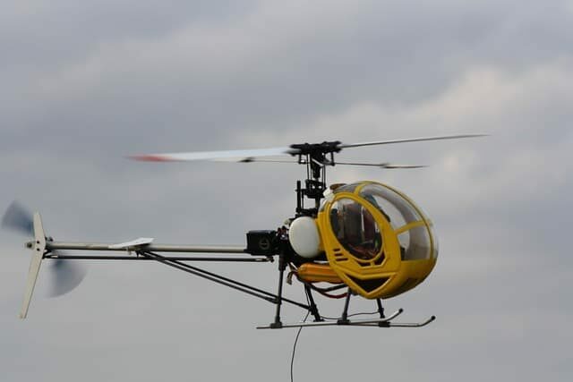
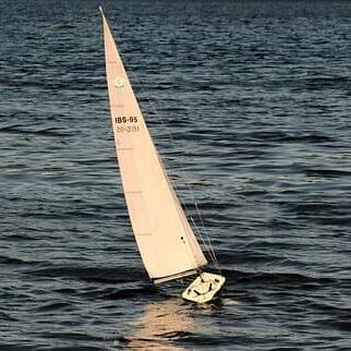
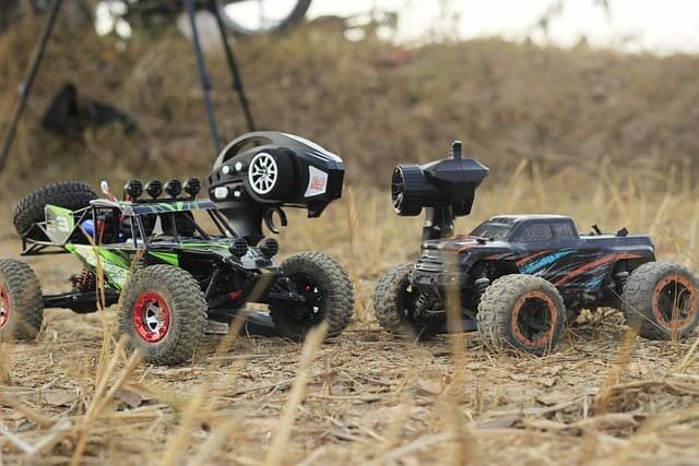
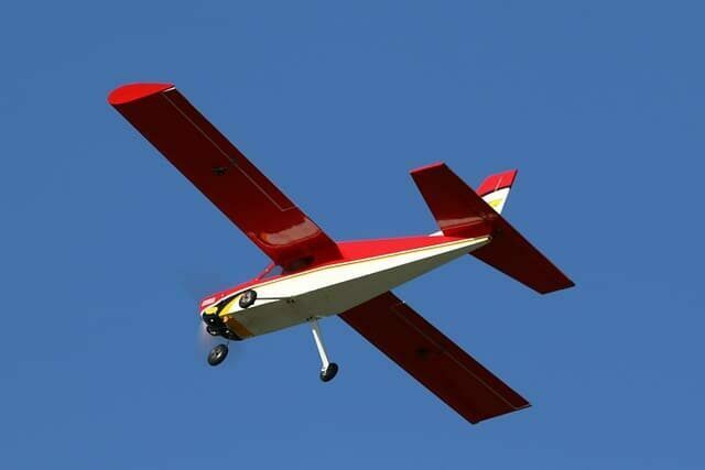
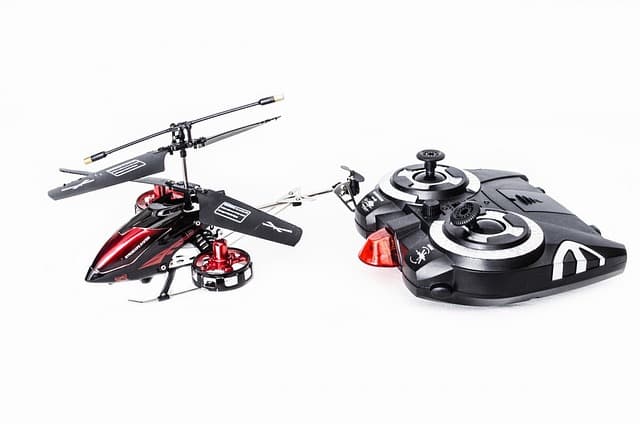
In the first weekend of the summer “Road to Records” will again gather radio-controlled model pilots and spectators of all ages on one site. Exciting spectacle: drones, planes and helicopters will fly in the sky and all-terrain vehicles,
boats and other vehicles will compete on land and water.
Children and adults can learn about new sports and high technology, watch the process of constructing air, ship and car models and evaluate the pilots’ skills. In addition, everyone can take part in test-drives and master classes on
making radio-controlled models.
An exciting race of drones and demonstration performances with the American 3D pilot Leonard Moffett from the R & D aviation sports club which specializes in the development and manufacture of flying radio-controlled models and mock-ups
of jets and piston planes.
The Program of the Holiday of Model-technical Sport “Road to Records”
12.00-18.00 – Flying Field – Race drones “”Road to Records”.
13:00, 15:00, 17:00 – FLYING FLOOR – Air Show with the 3D pilot Leonard Moffett and ASK “R & D” America.
14:00-17:00 – AVIA ANGAR – Tiny Whoop. Mini-drone convention among the strongest pilots .
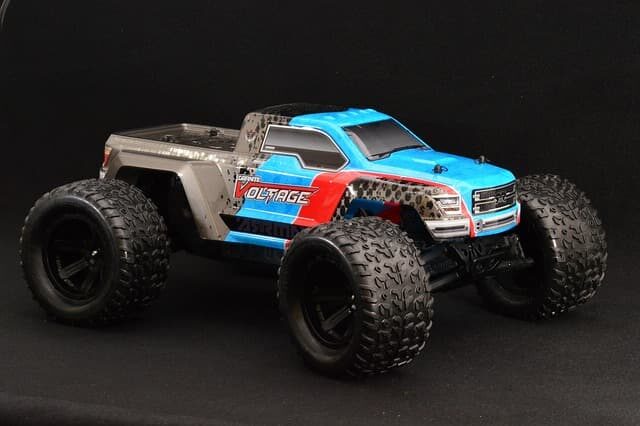
12:00-17:00 – AUTODROM – Racing of radio-controlled off-road vehicles, scale 1/10 (RC ORDA / FAMS).
12:00-17:00 – WATERWATER TRACKS – Test-drive of radio-controlled ship models for all comers.
12:00-16:00 – AUTOPOLIGON – Championship among radio-controlled racing trucks EuroTrak / Euro-truck / scale 1/14.
12:00-15:00 – TROFIPARK – Races and test-drive radio-controlled models of off-road vehicles on electric traction, the scale of 1/10 (RC TROPHY KHIMKI / HobbyCenter).
For visitors of the Park: admission to the event is free
Join us. It will only take a minute.
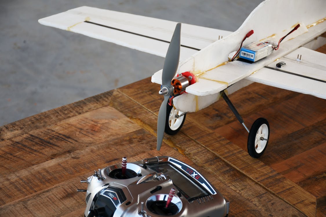
Radio-controlled models – it’s a whole world, only in miniature. Owning a personal fleet of cars and trucks, helicopters and airplanes, ships and submarines is a cherished dream of any boy.
Modelism – the child is not at all a game industry. The first radio-controlled models were created to test future full-size equipment. Now mini-versions help to solve tasks that ordinary planes and cars cannot do. For example, to deliver
medicine or mail in emergency situations to dangerous or hard-to-reach places. They are also involved in exploration work. In short, micro-products have macro capabilities.
Our Speakers


Our Reliable Suppliers

Are you looking for the perfect present for that special 35 year old woman in your life? Finding an appropriate and meaningful present can be tricky, so if you’re stuck for inspiration then we’re here to help!

Looking for a reliable and efficient bus rental service? At BCS Bus Charter Rental, we provide top-of-the-line charter buses for groups of all sizes. Our team of experienced professionals will ensure you have the safest and most comfortable travel experience.

Welcome to our exciting world of car coffee table books! At AutomoBible, we pride ourselves on bringing you something a bit different by looking at the car world in a new way.
Mercteil is the best place for Mercedez-Benz owners to find genuine performance parts for their vehicles. Mercteil carries a wide selection of parts and accessories, including exhaust systems, spark plugs, and high-performance filters
Spending time together on a bike ride is a wonderful way to bond with your kid. Your child can ride along with you and enjoy the scenery with the same perspective.
TireWheelGuide.com is a comprehensive guide to wheels and tire sizes, featuring a tire calculator and tire comparison tools. It provides detailed size charts and information for over 100 car brands and 3500+ models. If you’re uncertain about the right rims, their expert reviews and buying guides offer invaluable insights and recommendations.

Discover the ultimate online shopping destination with Shoppok, a leading e-commerce site that features a diverse selection of products, from cutting-edge electronics to trendy fashion items, and everything in between. With an intuitive interface, secure payment options, and speedy delivery service, Shoppok has quickly established itself as a go-to destination for savvy shoppers seeking convenience and quality.
187
projects
23,592
worked hours
14
Speakers
Latest news
The smallest radio-controlled car is made in 1:36 scale. It is only 11.4 centimeters in size and weighs less than a hundred grams. The model fits in the palm of a person’s hand. This baby is a limited edition and is of interest only
to collectors.

Do you still have questions?
Let us know!